Digital Rose Engine
This is a work in progress. I completed the first iteration a couple of years ago, finished some pieces, and then moved on to other things for a while. Lots more I'd like to do with this though, and I'm always looking for better ideas and input…
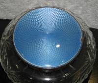
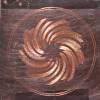
A little history. This photo shows guilloche enamelwork. It is a technique that probably originated with woodturners and was then famously incorporated into precious metal work by the Russian jeweler Faberge who added clear vitreous enamel coatings and used the technique in many of his famous eggs that were presented to the Russian royal family.
The same kind of patterning is often seen inside the more upscale (mechanical) old watches and clocks.
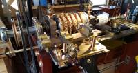
Through the early to mid 1900s the engraving was usually done with a variation of a “turning engine” that came to be known as the rose engine. One is pictured here. The acorn-looking white thing to the right is the piece being worked on. The machine is essentially a slow-turning lathe where the brass camwheels in the middle area push the chuck that holds the workpiece off center in a repetitive and reproducible manner while the cutting tool remains in place. And then there is a ton of stuff for indexing and depth control and who knows what else.
There are refurbished machines sometimes available for large pricetags and I believe a company making a modern version of the equipment. But where's the fun in that? My friend Bill (who taught me silversmithing and who get's himself and me into all manner of trouble) decided he wanted to build his own. From scratch. And after he got a basic prototype working he brought it in to the old studio to demo it.
The cam wheels push a rocker box back and forth, and as you can see from the pictured engine, every time you want a different pattern you have to create a new camwheel (Bill's first camwheel was hand-cut from lucite and was a project in and of itself). And it seemed like an obvious thing to propose using an arduino and a motor to push the rockerbox back and forth with a lot more flexibility. (Bill has since discovered that the original technology has been somewhat preserved by the Society for Ornamental Woodturners and plans for various cam designs are available, but before we know that, a digital test system to figure out how to eventually design the cams made sense). And of course that led to asking why not put all 3 motions (radial, Z, and rotation) under computer control? Bill said “you should give it a go” and someone was dumb enough to say “sure, why not?” ![]()
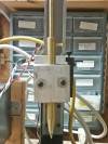
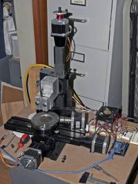
I was fortunate enough to have the guts of a sherline 3 axis platform that eliminated the need to figure out a lot of the mechanical side of it. And I had a rotary table that came with my Taig mill. After a few false starts I had a prototype with a Uno running three small stepper motors via Sparkfun easydriver boards and a spring-loaded pen holder.
Some very crude code drew this first image in Sept 2013.
A couple of weeks later I had some marginally less crude code and had figured out some things about step sizes and the like.
I had thought that simply using a scribe would give me the results I was looking for. I built a brass holder and some clamps that would press a carbide point against the metal with a spring to allow the point to float a little when the metal surface wasn't perfectly flat.
And the result was that the magic smoke escaped from one of the easydrivers. I upgraded the motors to 127 oz-in Nema 23 format steppers (which eliminated the need for weird adapters to mount them on the frame), moved up to Big Easy Drivers with heat sinks and a cooling fan, and a beefier power supply. The steppers can microstep at 320 steps per rotation. The rotary table is 72 turns per rotation (so 230,400 steps per turn or 640 steps per degree) and the leadscrews are 20 turns per inch, (64,000 steps). Seems like there is plenty of room to drop the odd step here and there without noticing it in the finished piece, especially as most designs will have a certain amount of progression as the concentric forms step towards the center. I was happy with the first results scratched through black sharpie in copper.
And then some really ugly enamelling.
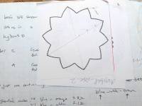
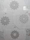
The petals of the flowers are pointed. Not at all what I wanted. Ugh–math!! But as with all math problems (at least the easy ones) once I decided it couldn't be impossible it really wasn't that bad. And it even immediately led to being able to do smooth wiggles, or pointy bits aiming in or out.
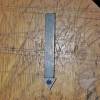
I used the spring-loaded scribe to scratch a couple of these in silver and enameled them with less ugly results, but I was not happy with these pieces (and in fact earlier this year the enamel cracked off of the one I actually mounted in a setting). The marks were just scratches. Fairly deep scratches admittedly, but a “metal smushed out of the way” groove lacked the reflectiveness of a cut face. And I kept breaking the carbide points off of the tips I was using (as in this photo). This burnished, shiny cut face is, BTW, one reason why you can't really do this kind of work on a router that has a rotating cutting bur or mill.
I continued to work on this project through 2014. The cutting problem eventually led me to metalworking lathe tools, and I found an inexpensive set at Harbor Freight that fit the bill. But the spring loaded holder didn't work with them, so the software had to extend to controlling the depth of the cut. Which necessitated very flat metal and a better way to hold it down.
But the cuts it produced have more of the shiny burnished look, and I was unreasonably excited when the shavings I was getting from the cuts seemed to cover an entire circuit of the piece.
(From arduino projects I've seen I should put a link to the code right around here, but there are some things too ugly even for the internet.) But the machine at this stage looks like this:
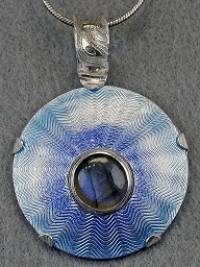
I cut a dozen or so pieces in silver. Enameled them a little better, and set most of them in etched silver or copper “turtle” settings.
Set in Silver with a moonstone.
In copper with a sparkly CZ.
And in silver with dichroic glass. (I bought a selection of these round glass cabs at one of the shows and just recently learned that I actually know Frank, the guy who made them!)
…and then I moved on to other projects. But Bill has been slowly plugging away at his mechanical version, and I'm back to thinking about this machine and trying to take it further:
Better holddowns to facilitate larger parts. Mark (at Southern Steel Fabrication) is machining me some plates that I think will hold down the pieces I'm cutting more securely, and also some larger, rectangular clamps.
In some pieces you can just make out tiny ridges where the code switches from radial to rotational steps. Smaller step increments should fix this and give a smoother wall to the cut.
Linear patterns. This should be “just a software” project. This is Faberge work again:
Patterns with “hard turns.” This is something that initially intrigued me about building this machine. In theory it should be able to turn at sharp angles rather than curves, which would open up patterns that are probably not possible using the traditional approach. This will probably necessitate being able to rotate the cutting tip which may be a tougher problem. But I think that the tip needs to rotate anyway: this close up shows that even with a cutter there is a lot of smearing going on which I'd like to fix.
Cutting on curved surfaces. Yeah, dream on Bob!
Camwheels for prototyping designs on Bill's mechanical system might be 3D printed fairly easily.
If it ran from a Pi or laptop could a real interface be built that would allow easier setup and previews of the results?

